Electric forklift controller circuit diagram, how much do you know?
Circuit diagram analysis of electric forklift controller
This article will analyze the circuit diagram of the electric forklift controller in detail, and analyze its working principle and debugging method in combination with the actual application scenarios.
Circuit principle
1. Power Circuit:
The controller adopts a regulated power supply circuit to convert the 36V voltage of the battery into 12V to supply power to the control circuit. The regulated power supply consists of TL431 and Q3, and the 12V supply voltage can be calibrated by adjusting the VR6.
2. PWM Generation Circuit:
The PWM circuit uses the TL494 pulse-width modulator as the core, and generates an oscillation frequency of about 12kHz through R3, C4, and the internal circuit.
3. Motor drive circuit:
The motor drive circuit is composed of Q1, Q2, Q4 and other components to control the permanent magnet DC brush motor. The width-shifting pulse output by TL494 is reversed-phase amplified by Q1 to drive VDMOS transistor Q2. The wider the low-level part of the widened pulse output of the (8) pin of the TL494, the longer the Q2 on-time and the higher the motor speed. D1 is the motor freewheeling diode to prevent Q2 breakdown.
4. Battery discharge indication circuit:
The discharge indication circuit uses LM324 chip, through four comparators, according to the change of battery voltage, to control the LED light to indicate the battery power status.
5. Battery over-discharge protection circuit:
When the battery voltage is lower than 31.5V, the (1) pin of LM324 outputs a low level, and the triode Q5 is turned on, forcing the TL494 to cut off the internal widening pulse output tube, and the motor stops running and enters the battery protection state.
6. Motor over-current protection circuit:
When the motor current exceeds the set value, the sampling voltage on the R30 exceeds the threshold, and the TL494 internal op amp 2 outputs a high level to stop the motor from running and protect the motor.
7. Brake Protection:
When braking, KEY2 is turned on, forcing the TL494 to cut off the internal widening pulse output tube, and the motor stops running.
debugging
During the debugging process, the speed regulation circuit, braking circuit, overcurrent protection circuit, and battery discharge indication circuit should be tested respectively to ensure the normal operation of each functional module.
Fuel level display circuit
The fuel display circuit uses the LM339 chip, which controls the LED light to turn on and off according to the change of battery voltage to indicate the battery level.
Improvement scenarios
Application scenarios
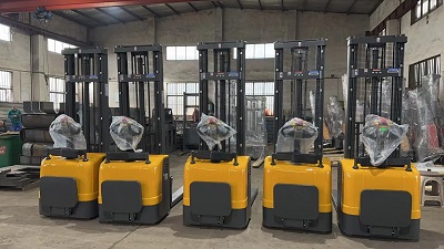
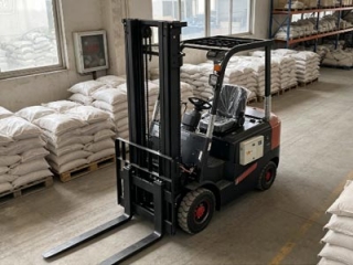
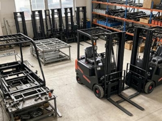
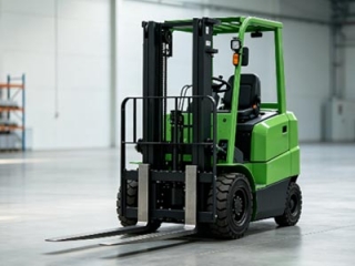
The circuit diagram of the electric forklift controller is widely used in various electric forklifts to control the speed, direction, braking and other functions of the motor to improve work efficiency and safety.
summary
This article analyzes the circuit diagram of the electric forklift controller in detail, and introduces its working principle, debugging methods and application scenarios. We hope to help readers better understand the design and application of electric forklift controllers.
Use Hall speed knob instead of photoelectric speed knob.
Use a microcontroller for more complex control functions
-
 GB3836-2021 Standard Explosion Proof Forklift Grade Price Difference AnalysisExplosion-proof forklifts for chemical warehouses follow Zone 1/2 and IIA/IIB/IIC standards. Zone 1 costs 20%-35% more than Zone 2, IIC adds 30%-40%. Pick proper grades to avoid overpaying or unsafe equipment.
Do you like ?0
Read more -
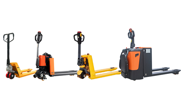
 Factory Direct Supply Compact Warehouse Electric Stacker & Truck Newnewton4000㎡ factory with full self-production of walkie/rider stackers, 3-wheel forklifts & pallet trucks, customizable. Transparent pricing, 15%-25% bulk discount, next-day delivery for Jiangsu-Zhejiang-Shanghai, 1-year warranty & on-site layout survey.
Do you like ?0
Read more -
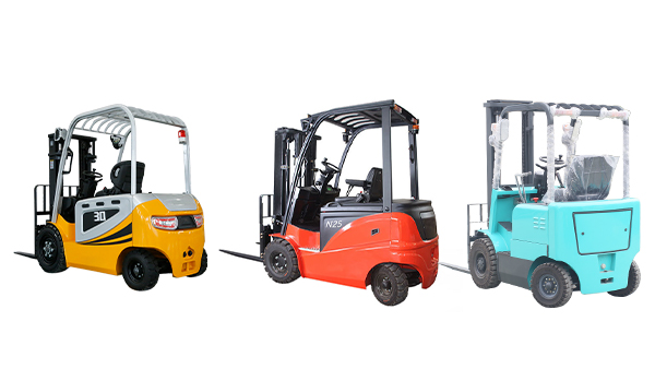
 Chinese & Imported Small Electric Forklift Brand Comparison For Compact StorageCost-effective lithium forklift guide for small warehouses: 8 domestic & 2 imported brands of stackers & pallet trucks with pros, cons & applicable scenarios. Budget buyers pick factory direct lead-acid/lithium models to cut warehouse costs.
Do you like ?0
Read more -
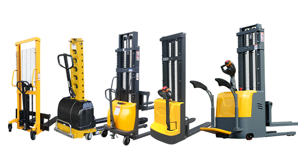
 Stand-on Electric Stacker Factory Direct Supply With Abundant Ready StockJiangsu local stacker factory with in-house welding & lithium lines. 1–2t stand-on lithium stackers in stock for 2.8m narrow aisles, non-OEM, same-day delivery for Jiangsu-Zhejiang-Shanghai. Customizable, 1-year warranty & 24h online service, export available.
Do you like ?0
Read more -
 Electric Forklift Brake System Maintenance 3 Practical Servicing Key PointsNeglecting forklift brake maintenance causes failure and deviation. Three key tips: never mix brake fluids, replace worn brake pads timely, bleed pipelines and adjust clearance after repairs to cut costs and avoid collisions.
Do you like ?0
Read more -
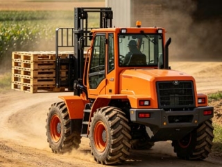 Is 2WD Rough Terrain Forklift High On Fuel Consumption | 2026 Real Test DataFuel consumption guide for rough-terrain forklifts in mines, farms and building yards. 2/3/5t 2WD diesel models consume 0.6–1L less per hour than heavier 4WD units, saving over 10,000 RMB yearly with 2000 working hours.
Do you like ?0
Read more