Speed Regulation Control of DC universal motor for Electric Forklift
1. Voltage regulation and speed regulation of DC universal motor of electric forklift. By changing the voltage Um at the motor end, for example, by swapping batteries in series or parallel; Alternatively, a resistor can be connected in series in the armature circuit, or two motors can be connected in series or parallel to change the speed n. The specific method is shown in the table below.
|
straight |
Speed Control |
Principle of speed regulation |
Speed regulation characteristics |
|
Battery series and parallel connection method |
Divide the batteries into two groups, and when the two groups of batteries are connected in series to parallel, the terminal voltage of the motor is reduced by half to achieve speed regulation |
This speed regulation method has no additional power loss, but the speed regulation is not smooth |
|
|
Series resistance method |
From the terminal voltage U=U-Ur=U-IR of the motor, it can be seen that when the power supply voltage U remains constant and the electrical current occasionally increases the resistance R, Um will decrease, and the motor speed n will decrease. Conversely, the speed will increase |
In the process of speed regulation, the speed regulation resistor will produce a large amount of power loss, which is generally not suitable for long-term operation; However, this method is still widely used in low-power electric motors due to its simplicity and convenience. Currently, the running motors in ordinary battery forklifts all use this speed regulation method |
|
|
Electric series and parallel connection method |
When two toe pullers, stinking silkworms, and hugging tablets are connected in parallel, the terminal voltage of each motor doubles, resulting in two levels of speed |
This speed regulation method does not have additional power loss, but can only obtain two levels of speed, so the speed regulation is not smooth. This method can only be used in situations where the production machinery is jointly driven by two motors of the same capacity, and is generally more commonly used in electric traction |
- Figure 1 shows the schematic circuit diagram.
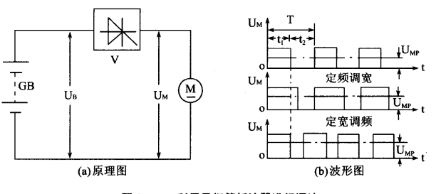
Figure 1
When the thyristor V of the DC universal motor of the electric forklift is turned on, its terminal voltage Um is equal to the power supply voltage U; When the thyristor V is turned off, the motor is disconnected from the power supply, and its terminal voltage Um is equal to zero. If the thyristor is periodically turned on and off at a certain speed, the terminal voltage Um of the motor will have a waveform as shown in Figure 2 (b). Assuming that the conduction time t of the thyristor is the width of the conduction time and the turning off time is the width of the turning off time, the average value Um of the motor terminal voltage is:Ump=Ut/ (t+t)=Ut;/ In the formula T=rU, T=ti+t2 is called the working cycle
R=ti/T, which is called the conduction ratio.
Therefore, by changing the conduction ratio of the thyristor, the average terminal voltage of the motor can be changed, thereby achieving the goal of speed regulation. There are three methods to change the conduction ratio:
(1) Fixed frequency and width modulation: the period T is fixed, and the conduction time width t1 is changed
Fixed width frequency modulation: t fixed, changing the cycle T, i.e. changing the operating frequency (2)
(3) Frequency modulation and width modulation: t both change.
The speed regulation methods of fixed frequency width modulation and frequency modulation width modulation mentioned above have been applied in future battery forklift circuits. In practical application circuits, a diode VD is also connected in parallel at both ends of the motor, called a freewheeling diode, as shown in Figure 2.
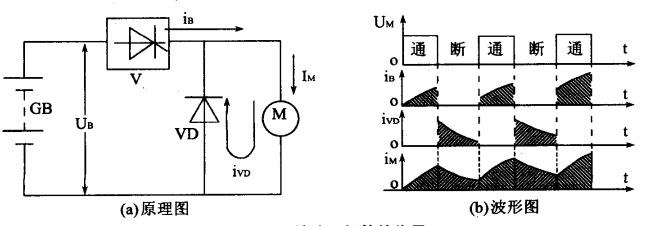
Figure 2
In this way, when the thyristor V is turned on, the current G supplied by the power supply GB to the motor will increase exponentially, and its waveform is shown in Figure 2-12 (b). When the thyristor V is turned off, the power supply does not supply current, i.e. iGB-0. However, due to the energy stored in the inductance of the motor winding, the motor current continues to flow through the diode VD, meaning that the waveform of the current i flowing through the motor M decreases exponentially. Therefore, the current Im flowing through motor M should be the sum of the power supply current ie and the continuous current i, i.e. Imi+iv, and its waveform is shown in Figure 2. It can be seen that after the DC universal motor of electric forklift is connected in parallel with the freewheeling diode, the conduction of the thyristor can be relatively small。
-
 GB3836-2021 Standard Explosion Proof Forklift Grade Price Difference AnalysisExplosion-proof forklifts for chemical warehouses follow Zone 1/2 and IIA/IIB/IIC standards. Zone 1 costs 20%-35% more than Zone 2, IIC adds 30%-40%. Pick proper grades to avoid overpaying or unsafe equipment.
Do you like ?0
Read more -
 Factory Direct Supply Compact Warehouse Electric Stacker & Truck Newnewton4000㎡ factory with full self-production of walkie/rider stackers, 3-wheel forklifts & pallet trucks, customizable. Transparent pricing, 15%-25% bulk discount, next-day delivery for Jiangsu-Zhejiang-Shanghai, 1-year warranty & on-site layout survey.
Do you like ?0
Read more -
 Chinese & Imported Small Electric Forklift Brand Comparison For Compact StorageCost-effective lithium forklift guide for small warehouses: 8 domestic & 2 imported brands of stackers & pallet trucks with pros, cons & applicable scenarios. Budget buyers pick factory direct lead-acid/lithium models to cut warehouse costs.
Do you like ?0
Read more -
 Stand-on Electric Stacker Factory Direct Supply With Abundant Ready StockJiangsu local stacker factory with in-house welding & lithium lines. 1–2t stand-on lithium stackers in stock for 2.8m narrow aisles, non-OEM, same-day delivery for Jiangsu-Zhejiang-Shanghai. Customizable, 1-year warranty & 24h online service, export available.
Do you like ?0
Read more -
 Electric Forklift Brake System Maintenance 3 Practical Servicing Key PointsNeglecting forklift brake maintenance causes failure and deviation. Three key tips: never mix brake fluids, replace worn brake pads timely, bleed pipelines and adjust clearance after repairs to cut costs and avoid collisions.
Do you like ?0
Read more -
 Is 2WD Rough Terrain Forklift High On Fuel Consumption | 2026 Real Test DataFuel consumption guide for rough-terrain forklifts in mines, farms and building yards. 2/3/5t 2WD diesel models consume 0.6–1L less per hour than heavier 4WD units, saving over 10,000 RMB yearly with 2000 working hours.
Do you like ?0
Read more