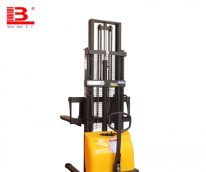
The gantry or fork frame of a reach forklift can move forward and backward. When moving forward, make the goods carried on the fork cantilever relative to the front wheel. Electric forklift manufacturers manufacture forward moving forklifts in two types: gantry forward moving and fork forward moving. The forward movement type of the gantry refers to the former driving the cargo fork forward during operation, extending beyond the front wheel to pick up or put down the goods; When walking, the cargo fork retracts the cargo, so that the center of gravity of the cargo is within the support surface.
Fork frame forward movement refers to the operation where the fork frame drives the cargo fork to move forward beyond the front wheel; When walking, the forks and goods retract back into the support surface, while the opposite is true when placing goods.
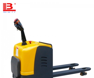
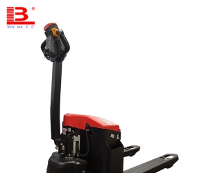
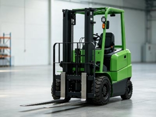
Reach forklift are mainly composed of battery packs, vehicle bodies, follow-up support wheels, drive wheels, bogies, drive motors, steering systems, hydraulic control rods, hydraulic pumps and motors, front wheels, etc; Structurally, it can be divided into four parts: forward moving mechanism, driving device, steering device, and braking device.
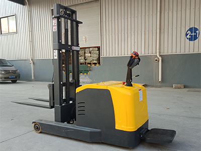
1. Move the mechanism forward. The forward moving mechanism of a forklift mainly includes two parts: the gantry forward moving mechanism and the cargo fork forward moving mechanism.
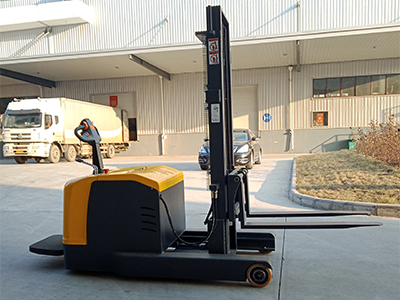
The front mechanism of the gantry has a forward moving wheel frame at the lower part of the gantry, which is equipped with two pairs of vertical guide rollers and two pairs of horizontal guide rollers, respectively arranged on both sides of the forward moving wheel frame; Four pairs of rollers roll in the forward leg track of the forward moving forklift. One end of the forward hydraulic cylinder is connected to the middle and lower part of the gantry, and the other end is relatively connected to the vehicle body, which can be pushed or retracted by the gantry.
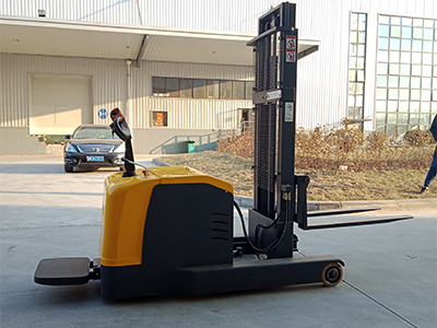
The rear frame of the reach forklift can be lifted and lowered in the gantry, and the cargo forks are hung on the front frame. The front frame and rear frame are connected by a scissor type linkage mechanism. When the hydraulic cylinder is pushed out, the shear fork connecting rod opens, and the front frame, along with the cargo fork, slides out towards the outside of the vehicle to complete the forward movement. On the contrary, when the hydraulic cylinder retracts, it completes the backward movement.
To enable the forks of a forward moving forklift to reach two rows of goods for stacking and dismantling operations, a combination of a forward moving gantry and a forward moving fork frame can be used, or a forward moving fork frame with a two-stage fork linkage mechanism can be used to increase the distance of the forks moving forward.
2. Drive device. The driving device of a reach forklift mainly consists of a driving motor and a driving wheel. The driving motor adopts a vertical arrangement, and the output end of the motor is adjusted to the set speed through a pair of oblique wheels and a pair of circular spiral bevel gears. The driving wheel is also a steering wheel and uses solid tires.
There is also a set of small diameter follow-up support wheels that are matched with the drive wheels, all of which are solid tires. In order to ensure good follow-up performance, electric forklift manufacturers usually maintain an eccentricity of 50mm~150mm between the axis of the follow-up wheel bracket bearing and the axis of the follow-up wheel. When the driving or following wheels encounter uneven ground, the rigid bogie can swing around its axis to maintain contact between the driving and following wheels and the ground. Due to the flat ground on which forward moving forklifts operate, the swing angle generally does not exceed 3. There are also types of elastic bogies, where the follower wheel bracket is connected to the bogie through springs, allowing the follower wheel to float up and down, with a floating stroke generally not exceeding 8mm.
3. Steering device. The steering device of reach forklift can be divided into power steering and mechanical steering, among which power steering can also be divided into hydraulic servo steering and electrical servo steering. The mechanical steering device mainly consists of a steering wheel, steering chain, rigid bogie, steering column, etc.
With the telescopic universal joint structure, when the bogie fixed on the bogie swings up and down with the rigid bogie, the steering wheel can still operate normally.
For forward moving forklifts using an electric servo steering system, the input shaft and output shaft are connected by an elastic device with a corner sensor, and the output torque of the steering motor is transmitted to the output shaft through a gear pair. During power steering, the angle deviation between the input shaft and output shaft generated by the angle sensor is eliminated by controlling the rotation of the steering motor. This device can also be manually turned, and the steering wheel is manually driven to rotate the wheel set. The electric servo steering system has a simpler structure compared to the hydraulic servo steering system, which can save 70% to 80% of steering energy consumption, and has low control force when manually turning, making it widely used.
4. Braking system. The braking system of a reach forklift consists of two parts: service braking and parking braking. The braking device mainly consists of a brake master cylinder, brake pedal, handbrake lever, brake oil box, brake plate, electric motor brake cylinder, electric motor disc brake pad, front wheel brake, and other devices. When braking, the brake pedal pushes the brake master cylinder, dividing the hydraulic fluid into two paths: one path is sent to the slave cylinders of the two front wheel brakes to open the brake and brake the front wheels; The other way is sent to the brake cylinder at the upper end of the drive motor to push the disc brake pads to brake the motor. When parking and braking, the brake hand pulls the steel wire to drive the pressure plate type brake pad under the brake pressure plate to brake the electric motor.
Usually, simplifying the structure of the service braking part can also meet the braking performance requirements of reach forklift . If the electric forklift manufacturer cancels the hydraulic braking part and does not take braking measures on the front wheels, only applies braking to the drive motor. The motor shaft end brakes used include pressure plate, shoe, or band brakes. In addition, the electric motor can also be assisted with reverse or regenerative electrical braking by the vehicle's electronic controller.
-
 GB3836-2021 Standard Explosion Proof Forklift Grade Price Difference AnalysisExplosion-proof forklifts for chemical warehouses follow Zone 1/2 and IIA/IIB/IIC standards. Zone 1 costs 20%-35% more than Zone 2, IIC adds 30%-40%. Pick proper grades to avoid overpaying or unsafe equipment.
Do you like ?0
Read more -
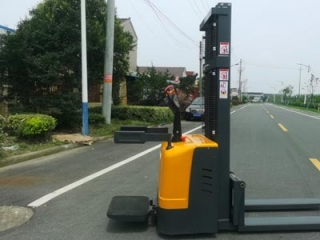
 Factory Direct Supply Compact Warehouse Electric Stacker & Truck Newnewton4000㎡ factory with full self-production of walkie/rider stackers, 3-wheel forklifts & pallet trucks, customizable. Transparent pricing, 15%-25% bulk discount, next-day delivery for Jiangsu-Zhejiang-Shanghai, 1-year warranty & on-site layout survey.
Do you like ?0
Read more -
 Chinese & Imported Small Electric Forklift Brand Comparison For Compact StorageCost-effective lithium forklift guide for small warehouses: 8 domestic & 2 imported brands of stackers & pallet trucks with pros, cons & applicable scenarios. Budget buyers pick factory direct lead-acid/lithium models to cut warehouse costs.
Do you like ?0
Read more -
 Stand-on Electric Stacker Factory Direct Supply With Abundant Ready StockJiangsu local stacker factory with in-house welding & lithium lines. 1–2t stand-on lithium stackers in stock for 2.8m narrow aisles, non-OEM, same-day delivery for Jiangsu-Zhejiang-Shanghai. Customizable, 1-year warranty & 24h online service, export available.
Do you like ?0
Read more -
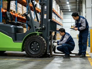 Electric Forklift Brake System Maintenance 3 Practical Servicing Key PointsNeglecting forklift brake maintenance causes failure and deviation. Three key tips: never mix brake fluids, replace worn brake pads timely, bleed pipelines and adjust clearance after repairs to cut costs and avoid collisions.
Do you like ?0
Read more -
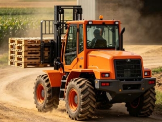 Is 2WD Rough Terrain Forklift High On Fuel Consumption | 2026 Real Test DataFuel consumption guide for rough-terrain forklifts in mines, farms and building yards. 2/3/5t 2WD diesel models consume 0.6–1L less per hour than heavier 4WD units, saving over 10,000 RMB yearly with 2000 working hours.
Do you like ?0
Read more