The circuit of an electric forklift shown in Figure 1 is a schematic diagram of the principle of a DC motor. The magnetic poles N and S are a pair of magnetic poles generated by the main magnetic pole, and the coil abcd represents the armature coil (winding); A and B represent inverters, small squares represent brushes, and U represents the applied power voltage. As shown in Figure 1:
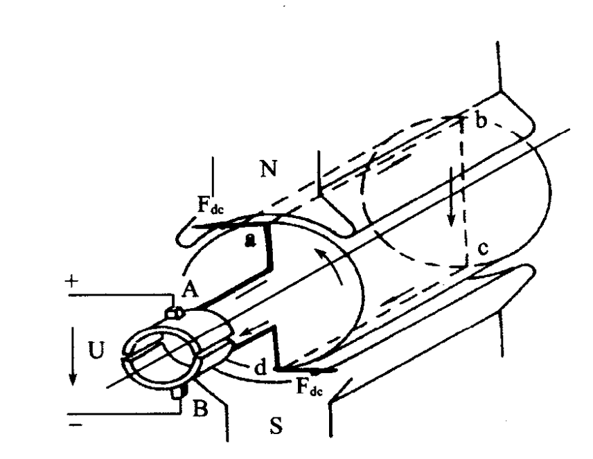
We know that the electrified conductor of an electric forklift motor is subjected to a force in a magnetic field, and the direction of the force is determined using the left-hand rule. The current on edge ab in the figure is from a-b; The current on the edge of cd is cd. Therefore, according to the left-hand rule, it can be determined that the force Fa on edge ab is to the left, while the force F on edge cd is to the right. Therefore, the coil abed is subjected to a counterclockwise rotation torque.
When the DC motor coil abcd rotates 180 degrees, the ab and cd edges align with the position shown in the diagram, and the commutator also rotates 180 degrees with the coil. As a result, the current direction of ab and cd edges is reversed. According to the left hand rule, it is determined that the force on edge cd is to the left, while the force on edge ab is to the right. The coil abcd is still subjected to a counterclockwise torque. Therefore, the coil, along with the armature core, rotates, which is the working principle of a DC motor. So, what factors are related to the torque received by the armature? From the working principle of an electric motor, it can be seen that the greater the magnetic flux generated by the main magnetic pole, the greater the current flowing into the armature winding, and the more windings the armature winding are, the greater the torque received. Since this torque is generated by the interaction between current and magnetism, we call it electromagnetic torque, represented by T. Obviously, the electromagnetic torque T can be expressed as follows:
T=CTIAφ
In the formula: C-and motor structure
I - Current in the armature;
φ— The magnetic flux of a magnetic field.
Due to the magnetic field lines generated by the armature winding (conductor) of the electric forklift DC motor cutting the main magnetic pole during rotational motion, an induced electromotive force is also generated in these windings (conductors). This induced electromotive force is opposite to the direction of the applied voltage, so it is called a back electromotive force, denoted as E. express. The magnitude of the back electromotive force EA is obviously related to the strength of the magnetic field and the speed of the rotation, and its expression is:
EA=CePn
In the formula: Ce - constant related to the motor structure;
Φ—— The magnetic flux generated by the main magnetic pole;
N-speed of an electric motor.
-
 GB3836-2021 Standard Explosion Proof Forklift Grade Price Difference AnalysisExplosion-proof forklifts for chemical warehouses follow Zone 1/2 and IIA/IIB/IIC standards. Zone 1 costs 20%-35% more than Zone 2, IIC adds 30%-40%. Pick proper grades to avoid overpaying or unsafe equipment.
Do you like ?0
Read more -
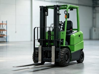
 Factory Direct Supply Compact Warehouse Electric Stacker & Truck Newnewton4000㎡ factory with full self-production of walkie/rider stackers, 3-wheel forklifts & pallet trucks, customizable. Transparent pricing, 15%-25% bulk discount, next-day delivery for Jiangsu-Zhejiang-Shanghai, 1-year warranty & on-site layout survey.
Do you like ?0
Read more -
 Chinese & Imported Small Electric Forklift Brand Comparison For Compact StorageCost-effective lithium forklift guide for small warehouses: 8 domestic & 2 imported brands of stackers & pallet trucks with pros, cons & applicable scenarios. Budget buyers pick factory direct lead-acid/lithium models to cut warehouse costs.
Do you like ?0
Read more -
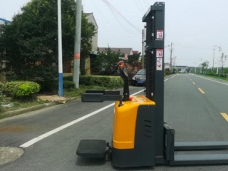 Stand-on Electric Stacker Factory Direct Supply With Abundant Ready StockJiangsu local stacker factory with in-house welding & lithium lines. 1–2t stand-on lithium stackers in stock for 2.8m narrow aisles, non-OEM, same-day delivery for Jiangsu-Zhejiang-Shanghai. Customizable, 1-year warranty & 24h online service, export available.
Do you like ?0
Read more -
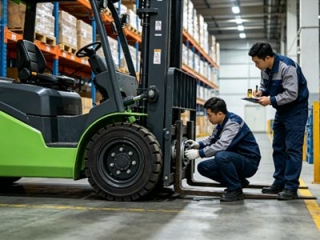 Electric Forklift Brake System Maintenance 3 Practical Servicing Key PointsNeglecting forklift brake maintenance causes failure and deviation. Three key tips: never mix brake fluids, replace worn brake pads timely, bleed pipelines and adjust clearance after repairs to cut costs and avoid collisions.
Do you like ?0
Read more -
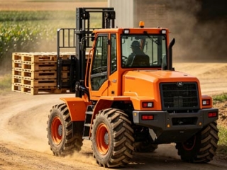 Is 2WD Rough Terrain Forklift High On Fuel Consumption | 2026 Real Test DataFuel consumption guide for rough-terrain forklifts in mines, farms and building yards. 2/3/5t 2WD diesel models consume 0.6–1L less per hour than heavier 4WD units, saving over 10,000 RMB yearly with 2000 working hours.
Do you like ?0
Read more