Brushless Motor Controller Principle & PWM/FOC Control for Electric Forklift
The motor controller acts as the core component of an Electric Forklift. Lack of relevant knowledge will bring obstacles to daily maintenance and fault repair. This article fully explains the Working Mechanism of Brushless Motor Controller for Forklift, elaborating the complete workflow of direction switching and speed regulation to deepen your understanding of electric forklifts.
Precondition: Core Hardware Composition
The whole speed & direction control system relies on four linked components for coordinated operation:
Control handle: Outputs 0–5V analog voltage signals to distinguish forward, neutral and reverse gears; voltage value corresponds to target driving speed.
Motor Hall sensors: Three groups of Hall sensors with 120° phase difference collect real-time position data of permanent magnet rotors and provide commutation reference for the main control chip.
Main control MCU chip: Receives handle operation instructions and Hall position signals, then calculates commutation sequence and PWM waveforms for speed adjustment.
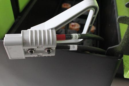
3-phase inverter power bridge: Consists of 6 groups of MOS power tubes. It executes MCU commands to switch power-on sequence of 3-phase windings and adjust output current.
Electronic Commutation (Core Advantage of Brushless System, Replacing Carbon Brushes)
Brushed motors rely on physical contact between carbon brushes to switch current, which easily causes abrasion and electric sparks. The brushless controller of the forklift adopts electronic commutation with zero mechanical friction throughout operation.
Hall sensors feed back real-time angle data of rotor magnetic poles; the MCU accurately judges the next power-on sequence of stator windings.
The MCU turns on/off MOS tubes of the 3-phase inverter bridge following a 6-step cycle logic to switch the current direction inside stator windings.
The stator generates continuous rotating magnetic fields to drive steady rotation of permanent magnet rotors. Commutation occurs every 60° electrical angle, delivering stable torque during startup and climbing without jitter or shaking.
Full Stepless Speed Regulation Process (Core Logic of Fast/Slow Control)
Speed regulation is realized via PWM pulse width modulation technology. Output torque and rotating speed are adjusted by changing the duty cycle of current conduction, combined with PID closed-loop dynamic adjustment algorithm.
Input target speed signal from handle: Larger handle deflection generates higher analog voltage, which the MCU identifies as high target speed; slight handle deflection outputs low voltage for low-speed precise rack alignment.
Closed-loop feedback of actual motor speed: The MCU calculates real-time motor rotating speed via Hall pulse signals, compares it with the target speed set by the handle and computes the speed difference value.
Dynamic adjustment of PWM duty cycle: If actual speed is lower than target speed, the MCU raises the PWM conduction duty cycle to increase average winding current, boost torque and accelerate rotation; if actual speed exceeds the set value, the duty cycle is reduced to cut output power for deceleration.
Working-condition adaptive speed regulation: The system automatically raises the duty cycle to output high torque during full-load startup and climbing; lowers the duty cycle to reduce power consumption during no-load flat-ground travel. Once the handle is released for braking, PWM output drops to zero instantly, and energy recovery is activated to recharge the lithium battery.
High-end electric forklifts are equipped with FOC vector speed control. The algorithm splits current into excitation component and torque component, realizing jitter-free low-speed operation and smoother linear speed adjustment for accurate alignment with warehouse racks.
After learning the above content, you will master the working principle of the core motor controller of Electric Forklift, as well as the speed change logic during daily travel. When the forklift malfunctions in the future, you can independently check faulty links to save troubleshooting time and avoid overcharged maintenance fees caused by information asymmetry.
-
 Export Forklift OEM Customization | CE Certified Electric Forklift SupplyNewnewton forklift factory offers standard OEM labeling & in-depth ODM customization for global clients. Complete CE document packages are supplied to manage compliance risks and meet overseas distributors’ procurement demands.
Do you like ?0
Read more -
 Newnewton Electric Forklift | Mini Electric Forklift Manufacturer SupplyStandard forklifts fail in old warehouses with narrow aisles, freight elevators and load limits. Newnewton mini 3-wheel forklifts feature 1.2-1.5m turning radius, leg-free design, custom options and CE certification for export.
Do you like ?0
Read more -
 Choose Narrow or Wide Leg Stacker? Pallet & Aisle Matching GuideRider stackers have 550mm narrow-leg and 680mm wide-leg versions differing in pallet compatibility, aisle requirements and stability. Select properly based on standard pallets and aisle size to avoid purchasing errors.
Do you like ?0
Read more -
 Walkie Straddle Electric Stacker | Advantages of Straddle Leg Full Electric StacWalkie straddle stackers fit narrow aisles of old warehouses with a 2.2-2.6m minimum working width, boosting storage space by 15%-28%. Low-cost and easy to operate, they suit high stacking operations on epoxy floors in small and medium warehouses.
Do you like ?0
Read more -
 LiFePO4 VS Lead Acid Electric Forklift Battery: Pros & Cons For Warehouse OperatDon’t compare battery prices alone. Based on China Forklift Network data, compare service life, charging performance and maintenance costs of lead-acid and lithium batteries to cut long-term operating expenses.
Do you like ?0
Read more -
 Heavy-duty Stacker Selection: Calculate Load Margin For High-level StackingStacker load capacity drops sharply at higher lifting heights, causing frame damage under long full-load operation. This article classifies load attenuation ratios under different lifting conditions and provides reasonable load margin standards for scientific model selection.
Do you like ?0
Read more